
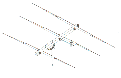
YAGI
The yagi
antenna is the most commonly used among the Beam variety. It's inventor
was mr Uda Yagi and there it has got it's name from.
The antenna exists of elements on a boom mostly from aluminum, though
i have seen copper ones aswell.
All the individual lengths are of influence of the antenna...this includes
element thickness This also counts for the height you have located the
antenna above your roof.
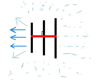
The Red line is called the BOOM the black lines are called: ELEMENTS.
Above is a simple drawing of a 3 elements yagi looking from the top at it.
The longest elements
is called a REFLECTOR. This side is often called the "Back of the
Antenna" and although it does "reflect" the signals coming
from the back of the antenna it also has a function in the Gain.
It is possible to have more reflectors on a single boom (ZX9-3ref is
a example.)
The second from
the back is the RADIATING element (the dipool) and is always shorter
than a reflector and longer than a director. This is where your coax
cable is connected. Most yagi's have an impedance of around 20/30 ohms.
Your coax cable was 50 ohms, so they don't match.
A impedance transformer is put on a yagi the in this case a Gamma match, but there are other types (hair-pin match, omega, t-match) More to this in the chapter connecting the coax to the antenna.
The Black line to the left at the above diagram, is called the first DIRECTOR. You can add as many directors as you want. All designs in chapter beams have 1 reflector 1 radiating element and 0 to 8 directors.
The most important
factor of a yagi is not the number of elements, but the boom length
!
The longer the boom the higher the gain !
It has no use to put 9 elements on a 10 meter boom, it is true that
a 6 elements on the same boomlenght will produce about the same signal.
A "standard" rule you can handle for gain, if you want 3 dB's more you need to double the boomlenght!
As just described
it is true: that with a full size yagi. Say a 3 element with a boomlenght
of 4 meter compared to a 4 elements with 4 meters boomlenght.
The 4 elements however will often produce a wider bandwidth and front
to side ratio's ! The forwarded gain however remains about the same.
You will need computer
programmers when you want to start modeling Yagi antennas. Free examples
are those from MMana or Yagimax.
Eznec is for example expensive but when u do use it a lot it is sure
worth the effort other programmers like 4nec2 are great but you do need
spare time to learn how to use it.
A big misjudgment by many is that they want to have there SWR as low
as possible cause they think the antenna performce only there is at
its best. This is false you can look at it like this:
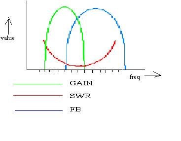
Not exactly of course but you get the general idea, the FB and Gain are not at their high values where the SWR is the lowest although many people think this is the case. So please do not worries to much about that SWR.
And you will not find one person who says: I changed the SWR from 1:7;1 till 1:1:1 and o boy....what a difference.!!..there isn't....
The Gain you might
expected from a yagi is shown in a diagram on the page beams.
Believe me thats it!
There is no way you might get 21,5dB (as some manufacturers would like
you to think) from a 8 element yagi measured the right way!
With that diagram
you can decide for yourself , which length of boom you need for the
wanted Gain.
The number of elements on it can be computer assimilated.
Perhaps you can choose between a small 5 el yagi or a large 4 elements
yagi and notice the difference isnt that great. I know guys who have
an 7 elements on a 6 meter boom, I would be more pleased with a 5 elements
long John with 9 meters boom in this case.
Materials
you should use:
All aluminum is suitable for building antennas though the aluminum called
: 6061 should have your preference due to it's anti corrosion, and electrical
components.
Dont forget aluminum exist of iron and copper and some other stuff.
The more copper you have the better it radiates but the weaker it gets...again
6061 (T-6) is the one almost all antenna makers use.
The thickness of
the radiating elements does influence the bandwidth, Gain, Front to
back of the antenna the thicker it is the wider the bandwidth
In the HPSD designs, I have used for all elements 22 mm thickness.
This means that the overall thickness of the element will have to be
22 mm it can be that the mid section is 25 mm and the tips end in 20
mm but overall 22 mm. A tapper-computer program can be used to calculate
if you are using the right thickness.
Finally you will need to know if the antenna is doing its job properly. Read chapter measurements and Gain to make your conclusion.
![]()