
RADIATION
PATTERNS, WHAT ARE THEY TRYING TO SAY ? AND WHAT CAN WE DO WITH THEM?
The radiation pattern of an isotropic in free space.
Free space is the world, without “earth or other things”
there is nothing for an antenna to radiate or “bounce” against.
This world does not exist. We often refer to “free space”
as the biggest benefit is the fact there is nothing, there is also “nothing”
that can influence our antenna.
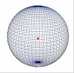
Lets say we have a single small spot which radiates in all directions
equal in a free space environment. The antenna his pattern would look
like the one above.
We call such an antenna an isotropic antenna; this is an antenna which
radiates in all directions equally. This antenna does not exist in real
live.
The shape of the pattern is similar to that of a round balloon or a
“round” earth.
Sadly the isotropic antenna doesn’t exist. So we are going to
have a look at the first “basic”
antenna and one which is actually simple to construct.
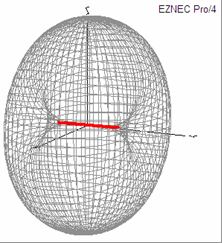
Above A dipole placed in ‘free space”.
The red line indicates the physical location of the “dipole as
you can see at the ends of the dipole the pattern is pushed inwards.
Please notice, there is NO Round pattern anymore.
The thing you need to realize is… If we start digging in the earth
we collect rocks/sand etc...that’s something we have to put somewhere
else. If we start to apply force on a balloon the balloon becomes smaller
in one direction but bigger in another. That’s the basic
of gain.
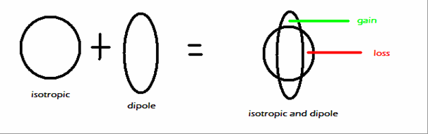
Okay, the above omni-directional pattern of the isotropic and the “pushed
Pattern” of the dipole both still in free space.
From the dipole its point of view, it has gain (green) in reference
to the isotropic.
If we compare the gain to an isotropic we call it “dBI”
if we compare the gain to a dipole it would be “dBD”.
The I stand for isotropic and D for dipole. Sometimes you will see gain
expressed just as “dB”. This is not useful. This doesn't
show to what its compared.
MOST IMPORTANTLY! THE DIPOLE HAS ALSO LOSS IN THE OPPOSITE DIRECTION!
We are now at our first step of conflict. You will hear many people
complain about false gain figures. You will hear people say gain should
be expressed in dBD since that is the only “real” antenna
we can compare to.
But…a dipole has gain in one direction and loss in the other)
Another thing is that a dipole “gains” ground gain
which can be almost 8,5 dBI
… So “the devil” can come up with different dBD figures.
It is known that we compare gain at the “maximum” points
of both and at equal heights etc etc. But not all people/companies do
that!
That’s why I prefer dBI…no where to hide, you can’t
“cheat”
LET
US INTRODUCE THE EARTH !
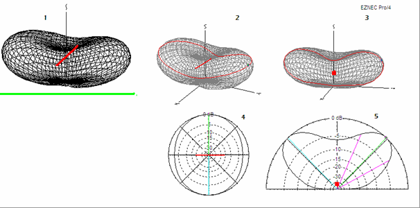
At the above picture nr 1, we have placed the dipole above real earth.
We might have noticed not only the “sides” are pushed outwards,
from our beautiful round shaped isotropic pattern, but also the “top/bottom”….
YES, hold that thought! You are right! If the pattern is “more”
pushed outwards…there must be additional gain somewhere else!
And loss at an other point!
My compliments, you have now learned, in real live (above real earth!)
a dipole produces more gain than it does in “free space”.
A valuable lesson which most people do not realize.
The amount of this “additional ground-gain depends on
the height above ground, polarization and ground circumstances.
Most plots so far were nice 3D plots. But that’s not what we always
see from our manufacturers.
We often see plots like nr “4” and “5”.
IF we look from the sky, down at our antenna the pattern
seen won’t be a 3D anymore. Just a 2D plot. This is called
the “AZIMUTH PLOT”. It's what we use with our rotator…”ill
turn the beam towards you! You will move the azimuth plot of the antenna.
The azimuth plot can be seen in picture 2 (the round circle) and picture
4.
The azimuth plot contains 360 degrees.
IF we look from the side to the antenna, the pattern we see
is called the “ELEVATION PLOT”. This plot can be
seen in picture 5. In real live the elevation plot is always 180 degrees
as the earth is underneath the antenna “blocks” the other
180 degrees.
We will investigate both plots to more detail!
THE AZIMUTH PLOT:
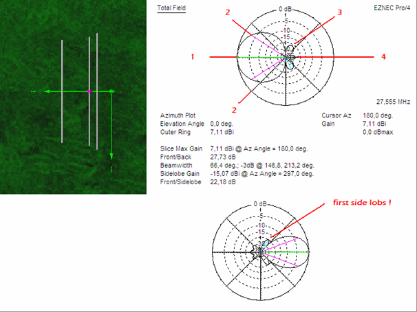
Back to the azimuth plot. We look from above, at the antenna…but
remember, its 3d in real live.
The pattern is not flat!
Nr1 This is the maximum gain we have. Most of our power
is directed in that direction.
In the eznec plot we can find this is 7,11 dBI
NR 2 These are the -3dB beam width points.
The points where the gain has dropped with -3dB compared to the maximum
gain number of the antenna. The beam width is expressed in degrees.
If your beam width is really small you will need to beam very accurate!
The -3dB points exist in the azimuth plain but also in the elevation
plain. Besides this, it tells us how “exact” we must aim
our yagi. It is also often used to calculate stacking distances. Which
is on another chapter on our website
HOW ACCURATE SHALL I BEAM?
Well, 6 dB is one S-unit. 3 dB is 0,5 S-unit. With the above beam (a
small 3elements) the -3dB beam width is 66,4 degrees. So there's either
33,2 degrees to the right and to the left before a station drops a half
S-unit…. So if you ever hear a station with a small beam ( 3 or
4 elements) say that he is not accurate beaming towards you, he is a
couple degrees off…let him know, you know better.
We are now going to talk about the back of the beam:
Nr 3, in the above picture, is the front to rear.
The front to rear figure, is the amount the signal
is suppressed over the entire back of the antenna,
over the full 180 degrees!
NR 4, in the above picture, is the front to back.
This is the figure which expresses how much the signal is reduced in
dB, opposite to the front (maximum gain, nr.1)
WAKE UP AND PAY ATTENTION!
WE LOVE TO SEE A HIGH FRONT TO BACK FIGURE IN OUR MANUFACTURERS ADVERTISEMENTS!
But more importantly would be to know what the entire back of the antenna
does.
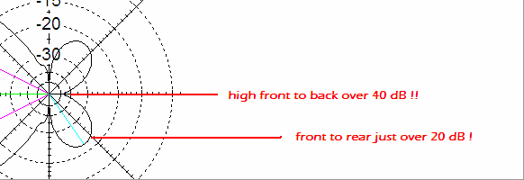
Most manufacturers don’t show antenna modeling plots. A good manufacturer
should do this, in my opinion.
In this case, the manufacturer could have advertised, front to back
over 40 dB! in the above yagi.
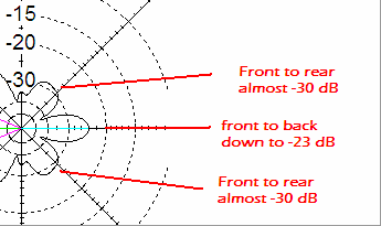
Most costumers are only interested in the front to back figure! But
if we take a closer look at the second yagi.
We notice the front to back of this one is only -23 dB but the front
to rear lobs are down to almost -30dB.
You may be the judge, of which you find a better “back”
of the antenna.
FIRST SIDE LOBS.
You might have noticed the second plot with the words “fist side
lobs”. As soon as a directional antenna becomes rather large,
roughly above a 6 elements yagi. The pattern will establish “side
lobs”. You might come across ads or other written documents which
say for example … the first side lobs are down -13 dB. This means
when you change your azimuth of the beam the signal will drop down and
come up again to a
maximum of -13 dB (compared to the maximum gain direction).
You will often read stories about first side lobs when it concerns stacking.
Stacking for maximum gain produces very large first side lobs. It might
sometimes be wiser not to stack for maximum gain but just slightly below,
so you will have smaller side lobs. We don’t want side lobs cause
they brings in “other stations” as well.
THE ELEVATION PLOT
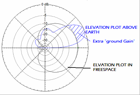
First a quick reminder. The elevation plot was when we were looking
at the side of the antenna. In the above plot you can see two “lines”
one would be the free space elevation plot (the black line) and the
blue line indicates the “real elevation plot” as we use
in our daily life.
Again we notice above real earth there is additional “ground-gain”
In this case the blue pattern has maximum gain at approximately 24 degrees
and is 11,75 dBI at that spot. The free space gain of this antenna is
only 7 dBI. So the “additional ground gain in this case at a 24
degree angle would be 4,8 dB.
And now back to the elevation plot.
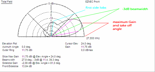
The elevation plot has a couple highlights of interest.
The -3dB BEAMWIDTH is equal to the azimuth plot but
now from a “sideward’s” perspective. In the above
picture the “main” force was at a 24 degree angle and 11,75
dBI. The bottom pink line is at 11,4 degrees and since it is a -3dB
beam width indicator the gain at 11,4 degrees is still 8,75 dBI!!
There are “side lobs” (blue). In this case
it is only a minor one, producing 13,84 dB straight up. If we had a
high placed yagi or a vertical antenna you might have seen many more
side lobs. In order to keep things straight I have picked one with minor
side lobs. These side lobs are more or less equal to the ones in the
azimuth plain. They are now seen from a “vertical” perspective.
Side lobs can come in handy as well.
First,
maximum gain point. If we stand outside and take a
look at the horizon the angle between earth and the angle we see is
more or less 0 degrees. If we rise our point of view slightly upwards
from the horizon (say looking at the sun a hours after sunrise) we have
an angle between the earth and the point where at that specific moment
the sun is.
The elevation angle is almost the same. At some point we are looking
towards the horizon… We adjust our spot slightly upwards…until
we reach the point where the antenna produces maximum gain. The angle
between the “earth” and that point is called THE
TAKE OFF ANGLE.
The abbreviation for take off angle is TOA. On 27 MHz the take off angle
is often used with earth as one point and the angle of maximum gain
at the other. It can however be that the take off angle is given from
another “point”. In the above plot the TOA of the antenna
is 24 degrees and the antenna produces 11,75 degrees at that angle.
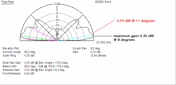
Above we have a 5/8 wave vertical at some height above earth.
The TOA is only 8 degrees, and maximum gain at that angle is 4,35 dBI.
At 11 degrees the antenna produces 3,74 dBI. Which was much lower compared
to our yagi at relative low height.
It would be important to remember that:
AN ANTENNA CAN HAVE A LOWER TAKE OFF ANGLE COMPARED TO ANOTHER,
THIS DOESN'T MEAN IT HAS MORE GAIN AT THE SAME ANGLE!
Why is the take off angle so important?
Well, it determines how strong you are at different locations around
the globe.
On 27MHz the propagation forms we use most often are F2 and E-skip (sporadic
E propagation). Around the earth there is a imaginary mirror reflecting
our waves back to earth.
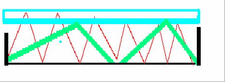
My apologies for the bad drawing, but infact it is quite spot on, what
is actually happening. At the left side we have a black vertical line
which translates a transmitting position. At the opposite right there
is a receiving point. Now the picture is “straight” but
needed to be bend in order to reflect the “real” world…but
for now we have work with this image The bottom black line represents
earth's atmosphere and the blue bar is the imaginary mirror (F2 layer
for example).
I have drawn two “radiation angles, a red and a green one. We
see that the angle between the green line and earth is small and the
angle between the red line and earth is large. The red line needs to
travel a much further distance in order to arrive at the location. This
distance means loss. There for the signal will be much weaker and perhaps
in real live not even audible.
So a LOW take off angle WILL PRODUCE A STRONGER SIGNAL FURTHER
AWAY
NOISE???
Imagine your transceiver without the coax connected…let’s
wait for a moment…yes, actually nice isn’t it? The noise
is low, no QRM no irritating noises, no QRM makers etc, etc.
Now let’s connect the antenna….Without propagation we notice
the “noise” floor rises. It is the
ENTIRE ANTENNA PLOT WHICH BRINGS IN THOSE NOISES.
And now, I won’t have to explain a lot. Imagine if we had no side
lobs, imagine if the -3dB beam width was really small, and imagine a
world with a fabulous front to rear.
What would that bring us…..yes…less noises more change to
work DX!
Kind regards,
Henry 19SD348
![]()
Copyright
by: www.hpsd.nl www.dx-antennas.com Version 1.01 Author 19SD348 Henry
HPSD