
Common-mode chokes (by G3TXQ)
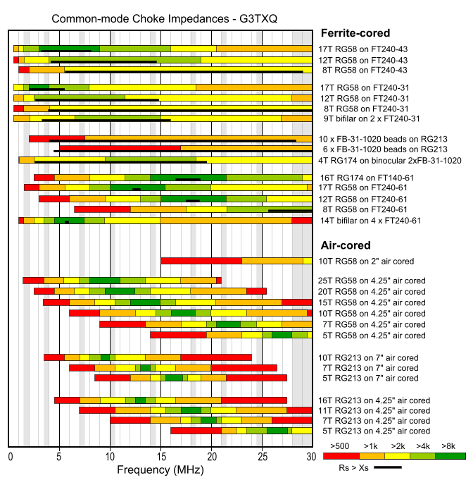
The following chart presents the results of impedance measurements made on a variety of common-mode choke implementations across the frequency range 1MHz to 30MHz. Amateur frequency allocations are indicated approximately by the vertical grey bands.
The colours of the bars indicate the magnitude of the CM (common-mode) impedance; however, depending on the style of choke and the type of ferrite material used for the core, that impedance might be mostly Resistive, mostly Reactive, or somewhere in between. The black bars at the bottom of the coloured bars indicate the range of frequencies over which the choke impedance is predominantly Resistive - that is Rs>Xs. No black bars are shown for the air-cored chokes because their impedance is almost entirely Reactive apart from a very small band of frequencies around resonance.
Reactive chokes have the disadvantage that they can "resonate" with a CM impedance path that is also reactive but of opposite sign - in some cases actually increasing the CM current flow rather than choking it; see the section at the bottom of this page for a detailed explanation. Resistive chokes have the disadvantage that if they have insufficient impedance to reduce the CM current to a very low value, there may be significant core heating.
Aim to choose a choke which has a high impedance and is Resistive over the frequency range of interest.
I hope to add more data as I make further measurements.
Why reactive chokes are undesirable
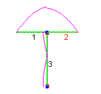
Let's take the example of a 20m half-wave dipole erected 30ft above average ground. It is fed by RG213 coax which drops vertically away from the dipole and whose braid is earthed at the “shack end” to a moderately effective 20O ground. The centre conductor of the coax is connected to the left-side dipole leg, and the braid to the right-side.
At the feedpoint, current flowing along the inside surface of the braid
will split - some will flow into the right-side dipole leg and some
will flow down the outside surface of the braid, depending on the relative
impedances of the two paths. The impedance of our coax braid path is
fairly high - about 28-j200O; the -j200 capacitive reactance arises
because the coax is short of an electrical half-wavelength. EZNEC predicts
that about 0.17A of the total 1A injected at the feedpoint will follow
the Common-Mode braid path, as shown on the right
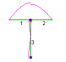
But if we now install a reactive CM choke at the feedpoint, and it happens
to have an inductive reactance of +j200O, we will cancel the capacitive
reactance of the braid path and create a fairly low impedance CM path
of just 28O; the braid current will then rise to 0.64A - that's a majority
of the current flowing at the feedpoint!
In this example an inductive reactance of +j200O is obviously a “worst case” and you would be unlucky if the choke was exactly that impedance; but note that any choke reactance between 0 and +j400 will reduce the CM path impedance - and therefore increase the braid current - to some degree.

However, if we install a 200O Resistive choke at the feedpoint instead
of a 200O Inductive choke we will effect an improvement, as shown in
the third diagram.
As we vary the length of the coax, the braid path impedance changes. When the coax is close to a quarter-wave long the CM path is high-impedance and relatively little current flows along the braid whether we include a choke or not; when it is close to a half-wavelength long substantial current flows if we don't include a choke. But there is no length of coax where an “unlucky” reactive choke impedance could not make things worse!
The situation gets more complex with a multiband antenna - in fact the potential for a Reactive choke exacerbating the situation on at least one of the bands increases.
The following
table shows for a range of coax lengths from 20ft to 70ft on this model
the braid current without a choke and with a worst-case inductive choke;
it also shows the impedance required in a Resistive choke to keep the
braid current 30dB below the level of the dipole current.
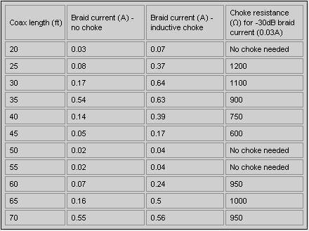
We note that:
For all
coax lengths a Reactive choke has the potential to increase the CM current,
sometimes by a very significant factor
Different values of choke Resistance are needed to reduce the braid
current, depending on coax length
We conclude that a high value Resistive choke is the safe option for
all scenarios. We also conclude that Rules-of-Thumb which equate the
required choke impedance to some multiple of the differential-mode load
impedance are unsound.
Thank you G3TXQ, for updates look on: www.karinya.net/g3txq/chokes/
In dutch;-):
Hallo,
Onderstaand verhaal
klopt niet geheel maar zo snap je hem wel...
(zo das ook een lekkere binnenkomer )
Om het even uit te leggen nemen we een dipool antenne...dat was immers zo'n beetje de basis van alle antennes.
Een dipool (zoals
het woord zegt bestaat uit twee polen die beiden gelijk zijn.
Beide zijdes zijn identiek....ze zijn in balans.
Nu is het ook de
bedoeling dat de antenne gevoed word met een signaal dat in balans is.
er moet op beide kanten van de dipool even veel "signaal "
staan.
Zie het maar als een koordanseres (type blond) met zo'n grote lange
stok beide kanten moeten even veel gewicht hebben anders valt ze...
Zover zo goed...
Nu komt de ellende:
Voor ons signaal overdracht van tranceiver naar antenne gebruiken we
een coaxkabel.
Die coaxkabel is niet in balans...Het is een "stok" die het
vrouwtje bv op 3/4 stuk beet heeft.
Shit zooi....dat vrouwtje op dat koortje is bijzonder aangenaam en dat
willen we dus niet hebben..
met andere woorden de stok van de vrouw is aan de ene kant wat korter
is geworden en dus uit balans is...
Nu hebben we twee
oplossingen:
1- we zorgen ervoor dat het vrouwetje stiekum een beetje terug word
gedrukt
2- we zorgen ervoor dat die stok van de vrouw aan beide kanten weer
gelijk is.
Met de eerste oplossing
"vernachelen" we de boel...we komen immers niet met een oplossing
maar we "gaan om" met het probleem. (de RF-choke/mantelstroom
filter).
De tweede oplossing zorgt ervoor dat alles echt weer in balans is...(onze
echte 1:1 balun).
Nou, wat gebeurt
er dus bij je antenne...
Het signaal komt "onbalanced" bij je antenne aan ( in theorie
zou het ook in balans kunnen zijn, echter in de praktijk komt dit eigenlijk
nooit voor).
Je antenne wou aan beide kanten evenveel "signaal" hebben...maar
goed dat kan dus niet want het signaal is niet in balans.
Tja...en waar moet dan "het signaal" heen....Het heeft maar
1 uitweg en gaat retour op je coax...en wel op de buitenkant van de
coax.
Dat signaal op de buitenkant van je coax noemen we "commen mode
currents...mantel stromen""
Dan kijken we even
weer naar die coax en het signaal op de heen weg.
Vanaf ons setje is het signaal weggestuurd...zoveel mogelijk in balans,
beide kanten heffen elkaar op en stralen dus niet..
+1 en -1 maken samen 0!
Maar goed nu hebben we een extra signaaltje retour...
+1 en -1 en +1...tja nu word het dus +1...
De coax gaat stralen...En dat moeten we niet hebben want die coax is
niet zo'n goed antenne!
Met alle gevolgen van die...slechte SWR...storing...etc...mischien zelfs
brandplekken op de coax.
er zijn trouwens
ook een boel dingen die die mantelstromen beinvloeden...
Zelfs de hoek van de coax..lengte daarvan etc, maar dit even terzijde.
De oplossingen hebben
we al aangedragen...
Wat doet die mantelstroom filter nu.
Die zorgt er voor dat die +1 gesmoord word (vandaar ook de engelse benaming
choke).
Hij doet dat door een hele hoge weerstand te vormen >1000 ohm. Hij
verpulvert ze!
Een mantelstroom filter is een goed middel voor mantelstromen het is
geen oplossing.
Het is ook geen balun want een balun (zoals het woord zegt) brengt dus
een signaal om van balanced naar unbalanced.
En dat is wel een "echte" oplossing.
Nu moet je er ook
niet "als de dood" voor zijn: Om bv op vakantie even een dipooltje
op te hangen zonder een 1op1 balun of mantelstroom filter is geen probleem.
Echter voor een langdurige oplossing is het wel aan te bevelen het kan
een boel problemen voorkomen.
Nou, eh zoiets?
Vr. gr,
Henry 19SD348
![]()