
Coax Cable:
![]()
![]()
Coax Cable does only need to do two things:
1) To take
the received signal from the antenna towards the receiver.
2) To bring the transmitted signal from the transmitter towards the
antenna is through a coax cable.
These are the only purposes of the cable.
Most commonly
used are RG-58, RG-213, Aircomm, Aircell.
There are bigger types like 3/8 or 7/8 hard line but this will cost
and perhaps it is of no use to use these types simply because the length
between your antenna and transceiver is short enough to there is hardly
any loss!
You might start thinking about those when you need more then 50 meters.
(At 11 meters I could not see the difference between 3/8 and Aircomm
Plus over 30 meters only in my wallet!)
Very lucky
we should be, that there are no big misunderstandings about cable. It
is as simple as:
Buy a line with the lowest cable attenuation
Do not make the cable any longer then necessary
The first highly depends on the money you would like to spent on cable.
Overall can be said that: the higher the cost the better the loss.
In extension
of the second there are misinterpretations by some, regarding "the
ideal length".
As said, you only have to keep one thing in mind, keep it as short as
possible.
WHAT
LENGTH?
As mentioned the best length is the shortest, in this way the loss due
to the cable is the lowest.
There can be one advantage by extending the length of the cable:.
A HALF WAVE coax cable or ANY multiple (1, 1½, 2 wavelength)
length of this will show you: "exactly the same input resistance
at both ends of cable". In normal words:
You can measure the exact SWR from the antenna with these lengths of
coax cable.
If your
antenna is truly 1:1 it doesn't matter, each SWR measurement anywhere
on the line and you will find 1:1.
Only when your SWR isn't 1:1 but higher your measurements will change
according to length, this is when it can come in handy to keep the line
a half wave long (or any multiple).
And there
are always SPECIAL CASES:
There are antennas which depend on the coax cable for the to produce
"the ground", some mobile antennas and very small bases verticals
could need this. Read the instructions before cutting them. Any full
size antenna does not have this problem! And just make sure you do not
use types mentioned before unless there is no way to overcome this.
When you want to combine antennas together(stacking) other features
come in, read the chapter Stacking.
OPTIMAL
LENGTH BETWEEN LINEAR / ANTENNA / TRANCEIVER ??
There are stories about the length between an amplifier and the antenna/
transceiver. The above goes for this as well.
Just keep it as short as possible, there is no benefit to make it anything
else
CABEL IMPEDANCE, Other figures
The cable has other characteristics: it has an impedance, power handling
capability.
Most commonly used is 50 ohm's cable.
Sometimes it could be useful to have 75 ohms (for stacking). Another
variety is: 300 ohms, this is what we call open line.
This was/is still in use for simple wire antenna's often multi band
antennas.
We will stick to the 50ohms, that's what we needed Flexible/ able to lay in corners etc!
The impedance
(50 ohms) of the cable is produced by it thickness, the distance between
the two conductors and the material between those conductors.
With the knowledge of this you can now make up your own mind, Is it
wise to bend coax cable in a tight curve?
No you just might changes the distance between the two conductors!
Do not bend the cable in straight curves (let the cable take the turn
it wants! no sharper, this also counts for storage)
When welded the cable, make sure there isn't a possibility for water
to enter the cable.(vulcanized tape)
POWER HANDLING CAPABILTIES:
The thickness of the inner cable is responsible for the power handling
capacities. The thicker the better.
RG58 witch is one of the thinnest cable can handel up to about 300..400
watts .
Any thicker size cable can handle 1 kw easy
( RG 213 about 1800 watts, Aircell 7 about 2,5 KW at 11 meters and Aircom
up to 5 KW.)
LOSS: with 100 meter length
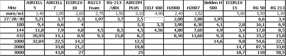
You can calculate easy with these numbers for example with only 20 meter
cable using RG-58 we come to
6,6 / 5 = 1,32 dB loss (100 meters RG 58 was 6,6 dB loss we want the
loss at 20 meters: 100/20=5 ..... 6,6/5= 1,32dB)
So when we stay below 50 meters Aircom Plus is good enough we only reach a loss of 0,75 dB then. (not included the connectors etc.)
 Aircell 7
 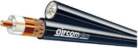 Aircom plus
CONNECTORS:
PL 259 is most commonly used type. although this type is not 50 ohms,
I know my mind is a bit extra-careful but I only use N-connectors these
are 50 ohms so any loss which just might exist with PL 259 connectors
is reduced. Honestly I have to say I never noticed any difference on
11 meters between those connectors.
Use only the amount of connectors you need and that is 2 !
Once's tested the S.W.R this will probably be the same next time. How
nice it is to see those needles going up, but again this is loss ...extra
connectors, S.W.R meter etc.
COAX AND VELOCITY FACTOR
The shielding and the core of a coax form a capacitor. Through the use of insulation material, the value of the capacitor is bigger then it would be in air, and this has the effect of slowing down the signal. This can be of great importance in some applications, although for many purposes it does not needed this information ;-)
Velocity
factor
The speed at which the signal travels is normally given the abbreviation
VF and this is the fraction of the speed at which the signal travels
when compared to a signal traveling in free space. So VF for a signal
traveling at the speed of light would be 1.0, and for one traveling
at half the speed of light it would be 0.5.
The velocity factor of the coax cable is found by VF = 1 / SQRT (dielectric
constant)
Coax
cable electrical length
One important factor of a coax cable in some applications is the wavelength
of the signals traveling in it. In the same way that the wavelength
of a signal is the speed of light divided by the frequency for free
space, the same is also true in any other medium. As the speed of the
wave has been reduced, so too is the wavelength reduced by the same
factor. So if the velocity factor of the coax cable is 0,66, then the
wavelength is 0,66 times the wavelength in free space.
In some instances lengths of coax cable are cut to a specific length
to act as an impedance transformed or a resonant circuit, then this
needs to be taken into consideration when determining the required length
of coax cable.
The advantage of using a coax cable with a low velocity factor is that
the length of coax cable required for the resonant length is shorter
than if it had a figure approaching one. For example, 1/4 lambda 75ohm
coax (VF * 1/4 lambda length) for transform the impedance from 125ohm
to 50ohm.
Dielectric
materials
There are different types of materials that can be successfully used
as dielectrics in coax cables. Each has its own dielectric constant,
and as a result, coax cables that use different dielectric materials
will show different velocity factors.
Coax
Insulation Material |
Dielectric
Constant (Er) |
Velocity
Factor |
Polyethylene |
2,3 |
0,659 |
Foam
polyethylene |
1,3
- 1,6 |
0,88 |
Solid
PTFE |
2,07 |
0,695 |
Dielectric constants and velocity factors of some dielectric materials used in coax cables.
Wire Beams
When using insulated wire for a wire beam you have to change the lenght. VF of the wire is between 0,98 and 0,95.
ANTENNA TUNERS
Do not use it.
If your antenna is not resonant at the design frequency and you need
an ATU to make sure the SWR stays below the wanted numbers. You have
done something wrong!
There is only loss in an ATU due to extra connectors, and the inside
of the ATU (coil/capacitor)
Most people use the antenna tuner directly after the transceiver, it
is only logical that the SWR does not become better It is NOT an ANTENNA
tuner but only a CABLE tuner!
Remember a dummy load had an SWR of 1:1,1 but was a terrible antenna
the same counts for an ATU.
The ATU is the joker in our system.
DONT USE IT!
ONE
EXEPTION:
There is only one way that the ATU may be used for what it is ment for.
That is with non- "conventional" types of cables and antennas.
(that 300 ohm line for example).
The case here is that these impedances are way of 50 ohms.
But neither will be used by 99,9 % of us 11 meter DXers.
PS Taking a look at most antennas, you'll often find coils in them. You could look at it as an actual "fixed antenna-tuner", but this is of course not what we are speaking about.
RECEIVING
PRE-AMPLIFIERS
The device, which can improve a received signal.
Works on 12 volts has an input and output connector (commonly PL259)
This for me is an un-know region at the 11 meter band.
In the new setup I will include one of the below marked pre-amps and
will put down the results.
Of course,i also had once such a device available from the CB-market,
only to find out the noise level was improving with great numbers perhaps
when I used bad cable it could have been an improvement.
The mentioned noise level is the quality figure of the pre-amp. At higher amateur frequencies these devices do come in handy because they do make up for all the loss in cable connectors etc. (I can notice a big difference on 144 mhz and 934 mhz)
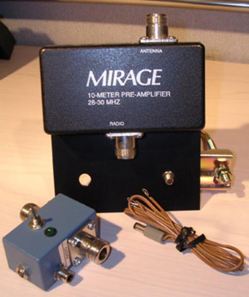
Professional
pre-amplifiers like those from MIRAGE or ICE have a noise figure of
< 1dB and a gain variable up to 20 dB.
The amount of power they can handle is not that high, Of course with
remote switches this is a problem you can overcome.
There is
only one reason why you should use a pre-amp
To make up for the loss produced by connectors and cables.
So often it is put where it should not be ....at the transceiver his
location, this could help in the old-days due to bad receivers but these
days the transceivers all are perfect and really do not need one.
The right location is at the bottom of the antenna, only then it might
bring stations a bit clearer.
Yes almost forgot: The signal which your antenna does not pick up, can
not be amplified by a pre-amp..
![]()